Skip to content Skip to sidebar Skip to footer

Rise Time In Control System

Ece 486 Control Systems

Ece 486 Control Systems

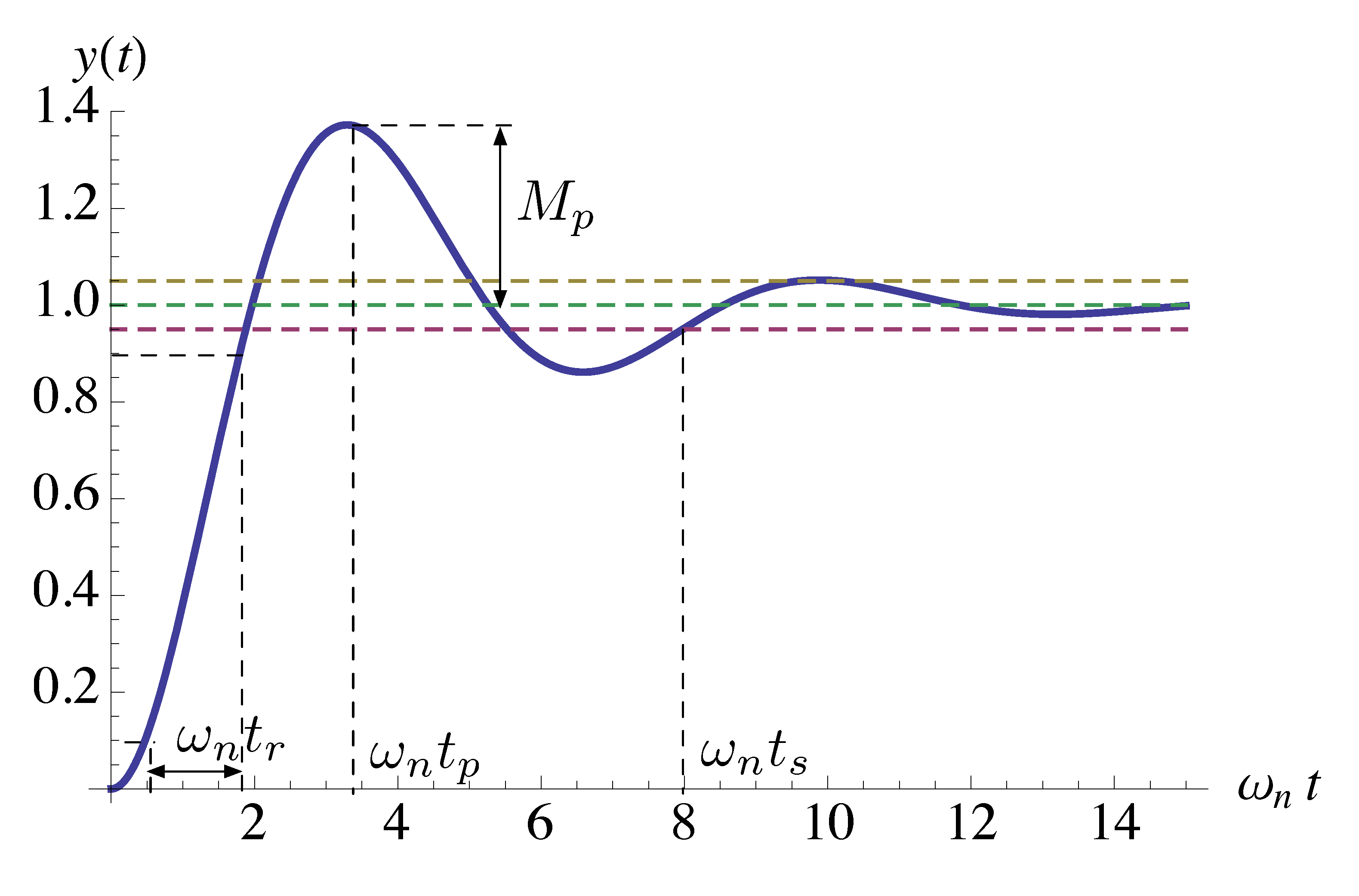
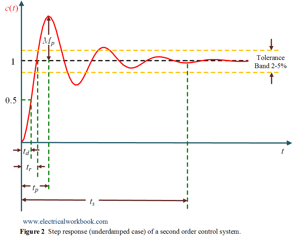
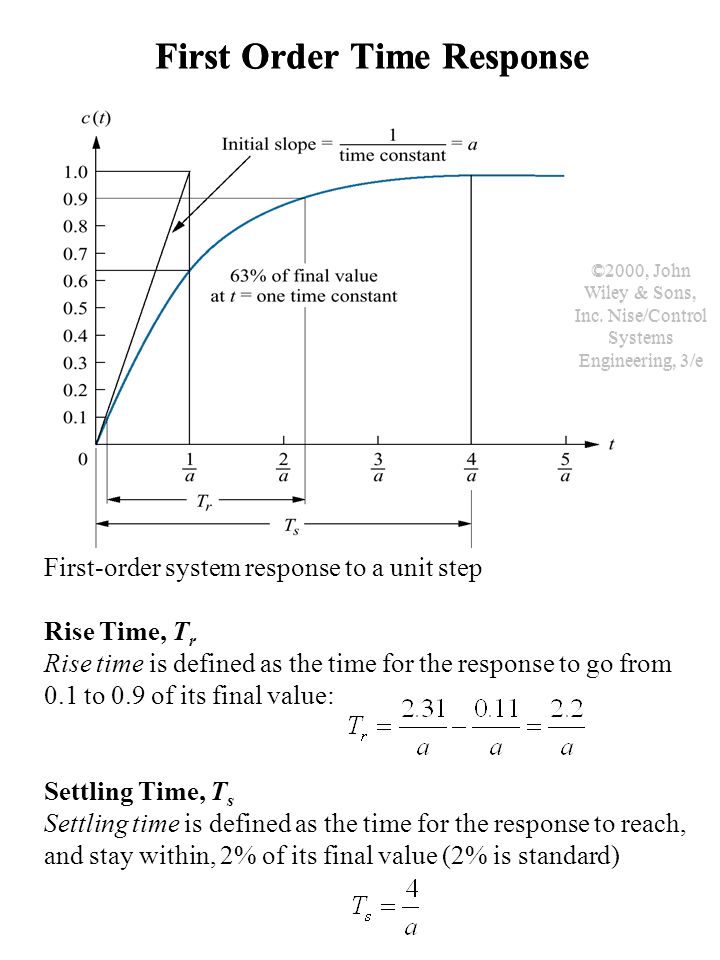
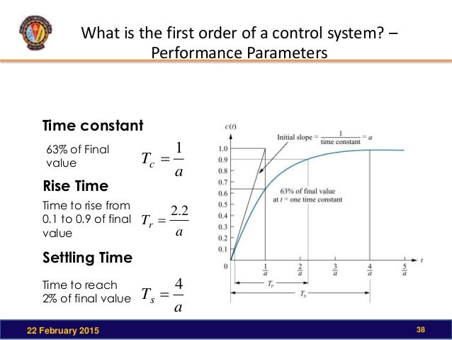
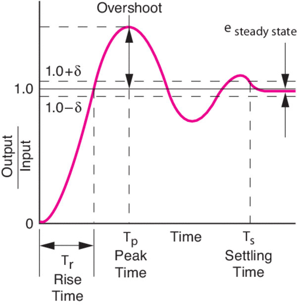
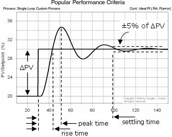
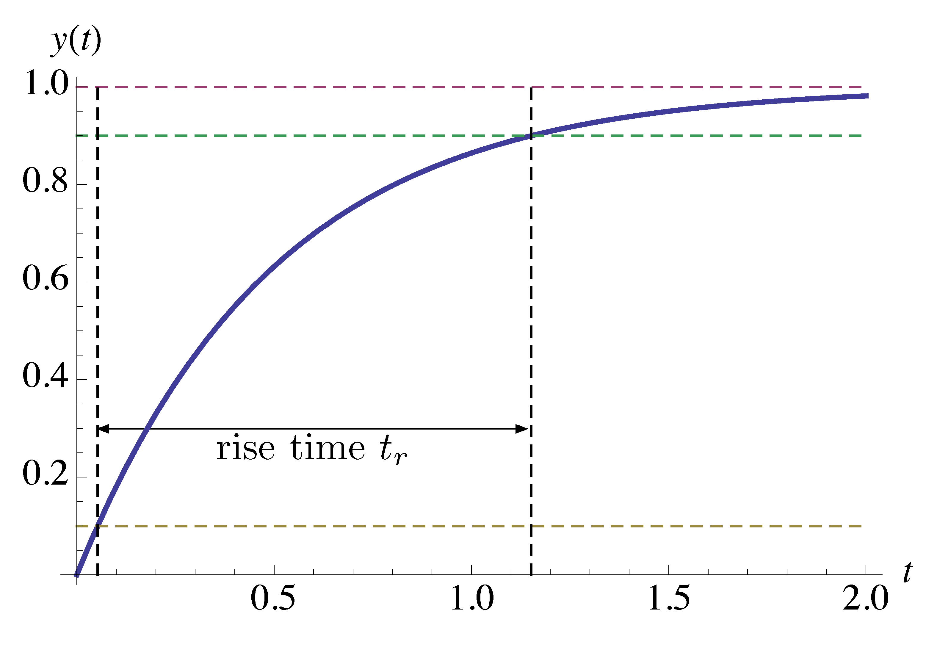
Rise time in control system. In digital systems it describes how long a signal spends in. Second order system rise time rise time formula rise time equation rise time for under damped system rise time calculation rise time control system. Rise time t_r The time needed for the response ct to reach from 10 to 90 of the final value for over-damped system or from 0 to 100 of the final value for underdamped system for the first time.

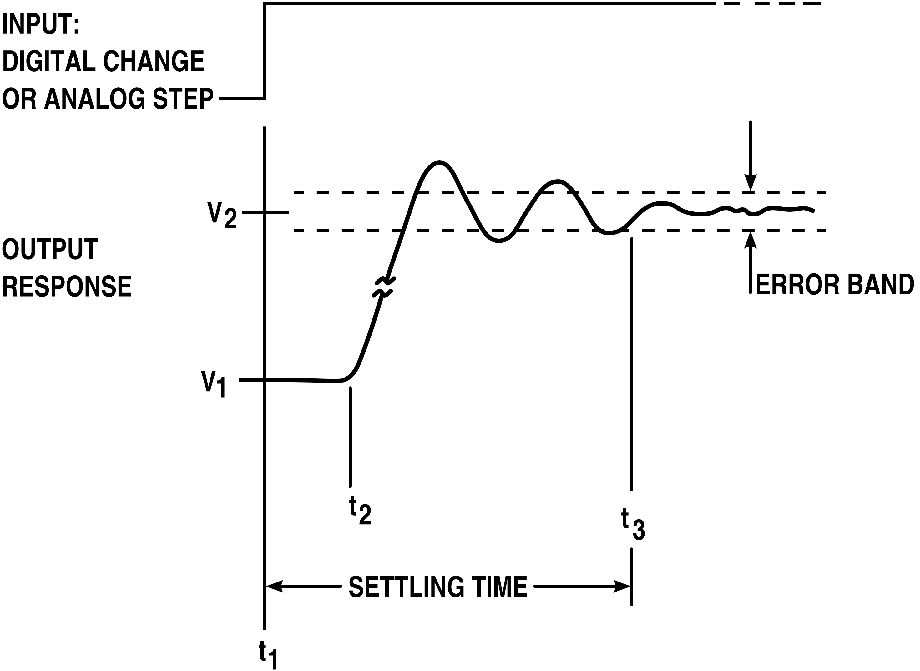
The settling time is the time required to achieve target. Delay time Td 2. Proportional P Integral I.

In most systems this would become the dominant time constant. By default the rise time is the time the response takes to rise from 10 to 90 of the way from the initial value to the steady-state value RT 01 09. Answer 1 of 3.

Second order system rise time. Strictly speaking the response time is the time that the control system WOULD TAKE to reach its steady state value IF it maintains the initial rate of change after delay time. The time required for the response to reach 50 of the final value in the first time is called the delay time.

158 rise time is defined as the time required for the response to rise from x to y of its final value with 0 to 100 rise time common for underdamped second order systems 5 to 95 for critically damped and 10 to 90 for overdamped ones. The purpose of a control system is to adjust the process variable to a desired state usually for the objective of minimising some cost. Rise time Tr 3.

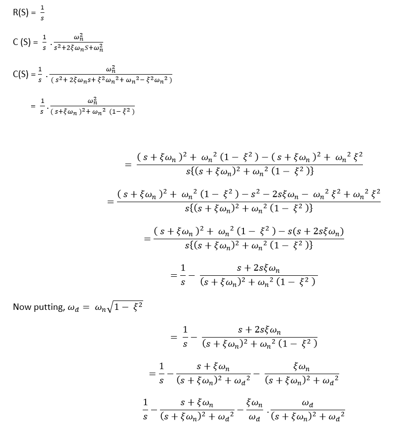
Rise Time The time required for response to rising from 10 to 90 of final value for an overdamped system and 0 to 100 for an underdamped system is called the rise time of the system. Peak time Tp 4. As we know there are three controllers.

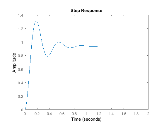
Rise time00248 settling time16091 overshoot 0626 peak time087. Reduce the settling time is not an easy task.

Time Domain Specifications

Time Domain Specifications

Rise Time Settling Time And Other Typical Second Order Step Response Download Scientific Diagram

Rise Time Settling Time And Other Typical Second Order Step Response Download Scientific Diagram

Time Response Of Second Order Control System Worked Example Electrical4u

Time Response Of Second Order Control System Worked Example Electrical4u

Intro To Control 9 1 System Time Response Terms Youtube

Intro To Control 9 1 System Time Response Terms Youtube

Control System Time Response Of Second Order System Javatpoint

Control System Time Response Of Second Order System Javatpoint

Settling Time Wikipedia

Settling Time Wikipedia

First Order Control System What Is It Rise Settling Time Formula Electrical4u

First Order Control System What Is It Rise Settling Time Formula Electrical4u

Ece 486 Control Systems

Ece 486 Control Systems

Rise Time Settling Time And Other Step Response Characteristics Matlab Stepinfo Mathworks India

Rise Time Settling Time And Other Step Response Characteristics Matlab Stepinfo Mathworks India

Overshoot And Undershoot In Servo Control Systems

Overshoot And Undershoot In Servo Control Systems

Help

Help

Control System Time Response Of Second Order System Javatpoint

Control System Time Response Of Second Order System Javatpoint

Rise Time In Step Response Underdamped Case Of A Second Order Control System Electricalworkbook

Rise Time In Step Response Underdamped Case Of A Second Order Control System Electricalworkbook

Time Response Of Second Order Control System Worked Example Electrical4u

Time Response Of Second Order Control System Worked Example Electrical4u

Transient Behavior Of A Control System Electrical Engineering

Transient Behavior Of A Control System Electrical Engineering

Transient Response Time Response Analysis Control System Notes

Transient Response Time Response Analysis Control System Notes

Control System Time Response Of Second Order System Javatpoint

Control System Time Response Of Second Order System Javatpoint

2

2

Step Response Of Position Control System At Full Load Download Scientific Diagram

Step Response Of Position Control System At Full Load Download Scientific Diagram

Pid Feedback Controllers Pid Shen Guojiang Institute Of

Pid Feedback Controllers Pid Shen Guojiang Institute Of

It Is The Time Response Of A System To An Input That Sets The Criteria For Our Control Systems Many Quantitative Criteria Have Been Defined To Characterise Ppt Download

It Is The Time Response Of A System To An Input That Sets The Criteria For Our Control Systems Many Quantitative Criteria Have Been Defined To Characterise Ppt Download

Settling Time Wikipedia

Settling Time Wikipedia

Csl9 4 F15

Csl9 4 F15

1

1

2

2

Rise Time Settling Time And Other Step Response Characteristics Matlab Stepinfo

Rise Time Settling Time And Other Step Response Characteristics Matlab Stepinfo

Control Systems Online Presentation

Control Systems Online Presentation

2

2

Step Response Of A System Overshoot Rise Time Setting Time Control System Matlab Youtube

Step Response Of A System Overshoot Rise Time Setting Time Control System Matlab Youtube

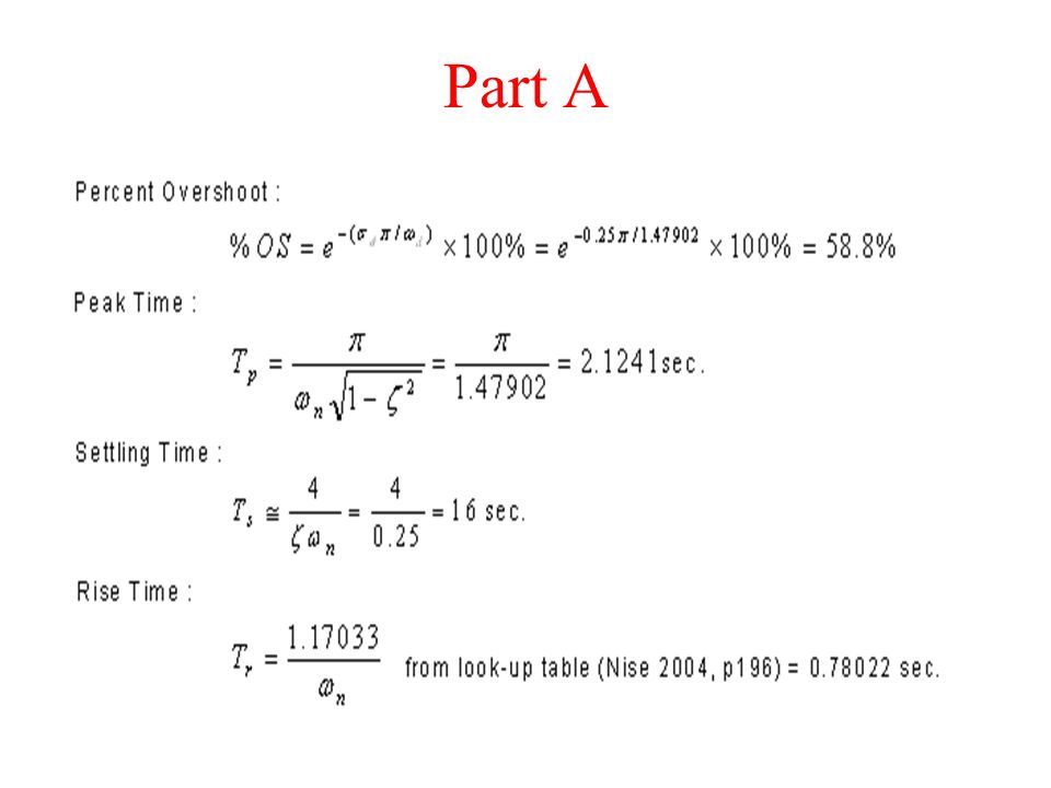
Feedback Control Systems Ppt Video Online Download

Feedback Control Systems Ppt Video Online Download

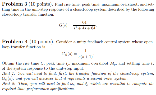
Solved Problem 3 10 Points Find Rise Time Peak Time Chegg Com

Solved Problem 3 10 Points Find Rise Time Peak Time Chegg Com

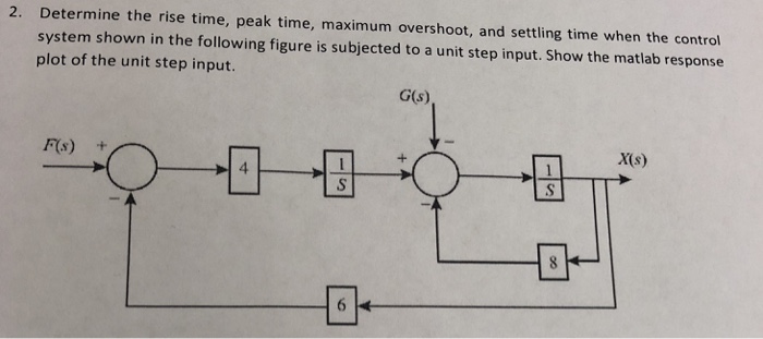
Solved 2 Determine The Rise Time Peak Time Maximum Chegg Com

Solved 2 Determine The Rise Time Peak Time Maximum Chegg Com

Control System Time Response Of Second Order System Javatpoint

Control System Time Response Of Second Order System Javatpoint

Comparing Controller Performance Using Plot Data Control Guru

Comparing Controller Performance Using Plot Data Control Guru

Time Response Of Second Order Control System Worked Example Electrical4u

Time Response Of Second Order Control System Worked Example Electrical4u

Nuaa Control System Engineering Ppt Video Online Download

Nuaa Control System Engineering Ppt Video Online Download

The Design Philosophy Of The Cnf Tracking Control Received 1 February Download Scientific Diagram

The Design Philosophy Of The Cnf Tracking Control Received 1 February Download Scientific Diagram

Control Theory Terminology

Control Theory Terminology

Transient Response Specifications

Transient Response Specifications

System Time Response Geeksgod

System Time Response Geeksgod

Control Tutorials For Matlab And Simulink Introduction Pid Controller Design

Control Tutorials For Matlab And Simulink Introduction Pid Controller Design

Rise Time Control Systems Exam Docsity

Rise Time Control Systems Exam Docsity

2

2

Rise Time In Step Response Underdamped Case Of A Second Order Control System Electricalworkbook

Rise Time In Step Response Underdamped Case Of A Second Order Control System Electricalworkbook

Comparing Controller Performance Using Plot Data Control Guru

Comparing Controller Performance Using Plot Data Control Guru

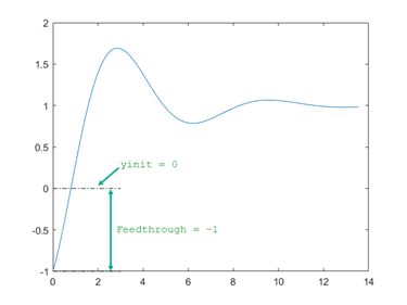
Time Domain Characteristics On Response Plots Matlab Simulink Mathworks Australia

Time Domain Characteristics On Response Plots Matlab Simulink Mathworks Australia

Time Domain Specifications Of In Control System Electronics Engineering Study Center

Time Domain Specifications Of In Control System Electronics Engineering Study Center

Estimating The Overshoot Rise Time And Settling Time

Estimating The Overshoot Rise Time And Settling Time

1

1

In most systems this would become the dominant time constant.

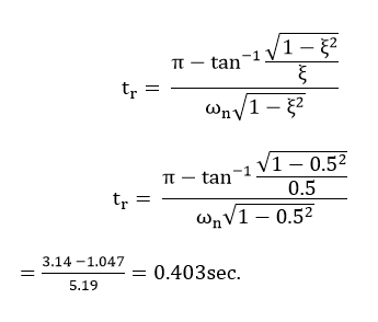
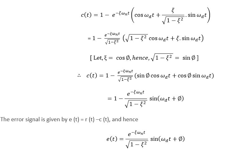
As we know there are three controllers. The rise time t_r occurs when time response ct reaches to unity for the first time so at t t_r ct_r 12. In most systems this would become the dominant time constant. Time-Domain Analysis and Design of Control Systems 210 1. Practically it would be For system. This is typically the 10-90 or 20-80. In case of over damped systems where the value of ζ is greater than one in this case rise time is defined as the time required by the response to reach from ten percent value to ninety percent value of final value. Step response of a system Overshoot Rise time Setting time Control system MATLAB - YouTube. For applications in control theory according to Levine 1996 p.


Peak time Tp 4. Answer 1 of 3. Rise time refers to the time it takes for the leading edge of a pulse voltage or current to rise from its minimum to its maximum value. Strictly speaking the response time is the time that the control system WOULD TAKE to reach its steady state value IF it maintains the initial rate of change after delay time. Maximum overshoot Mp 5. For a signal in the time domain an important figure of merit is its rise time. Step response of a system Overshoot Rise time Setting time Control system MATLAB.
Post a Comment for "Rise Time In Control System"